
STEAM ENGINE
Steam engines are the most powerful source of kinetic energy in the mod.
In fact, a max-level steam engine can reach 294,912 SU.
Yes, I said levels — the power of steam engines (or boilers) is measured in levels
(as well as SU), as you can guess: the higher the level, the more SU and RPM
it produces.
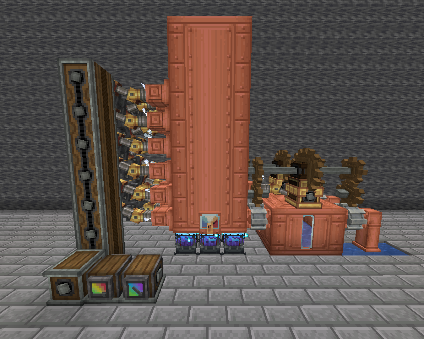 |
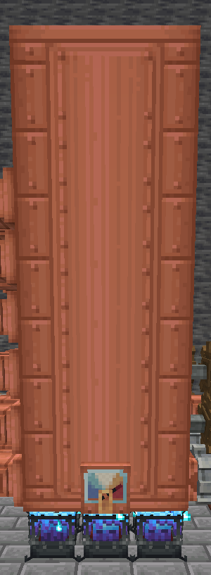
| Here’s an example of a max-level boiler |
At first glance, it may seem confusing, but in reality, it’s very easy to
understand.
Let’s break it down into sections so it’s easier both to understand and to explain:
1. OUTPUT SU AND RPM
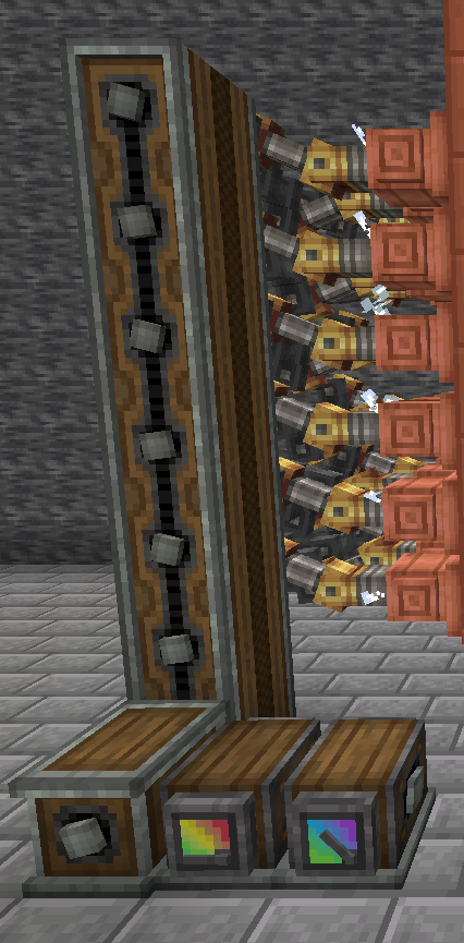 |
| This is what it looks like |
This section is the one that will connect to the system and will provide
it with power (SU) and, in some cases, also speed (RPM).
There are several blocks, each with its own function:
- 18 steam engines
- 18 shafts
- 9 encased chain drives
- 1 horizontal transmission (gearbox)
- 1 speedometer/stressometer
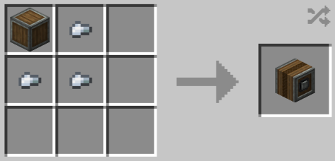
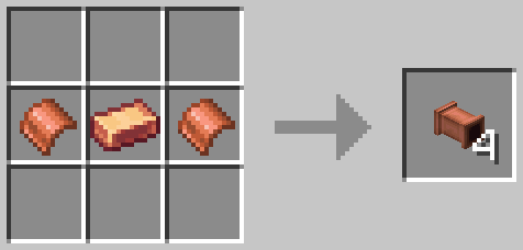
STEAM ENGINE (BLOCK)
Steam engines are the ones that produce SU; they need to be connected to
a boiler and, to transmit the kinetic power they generate, to a shaft.
For a level 18 boiler (the maximum level), at least 18 steam engines are
needed to generate all the potential kinetic energy. If you place more than
18 engines, the SU of each engine will be:
294,912 SU (the maximum a level 18 boiler can generate) divided by the number
of steam engines.
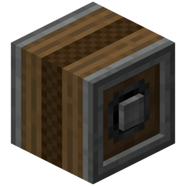
 |
| Here’s what a steam engine looks like |
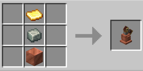 |
| And this is the recipe |
Each steam engine in a boiler is independent from the others. As you can
see in the image of the level 18 boiler, I placed an engine at the back
to power the pumps that feed water into the boiler. In fact, engines can
be placed anywhere around the boiler you want.
Each individual engine generates between 2,048 SU and 16,384 SU and can run
at a minimum of 16 RPM up to a maximum of 64 RPM.
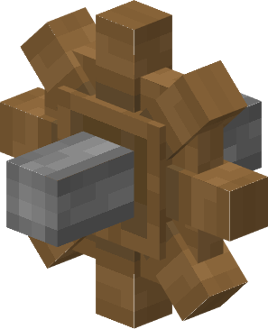
SHAFTS
Shafts are used, as mentioned earlier, to transfer, in this case, the kinetic energy produced by the steam engines to the coated chain drives.
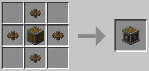
ENCASED CHAIN DRIVES
Encased chain drives are shafts that can transfer kinetic energy both horizontally and vertically.
 |
| Here’s what an encased chain drive looks like |
 |
| And this is the recipe |
They are not crafted only with iron nuggets, but also with zinc nuggets. This makes them easier to craft, because if you don’t have one material, you can use the other.
HORIZONTAL / VERTICAL TRANSMISSION (GEARBOX)
Gearboxes are used to distribute the kinetic force input on one side to
three other sides, but in the opposite direction of rotation. Depending
on the type (horizontal or vertical), it distributes the rotation; in
this case, it distributes it horizontally.
It can be connected to a shaft and will not consume any SU, and the other
outputs will rotate at the same speed.
 |
| Here’s what a horizontal gearbox looks like |
 |
| And this is the recipe |
To craft the vertical version, simply place the horizontal gearbox in the crafting grid, and you will get the vertical gearbox.
SPEEDOMETER / STRESSOMETER
We have already talked about
both,
but in the following chapters there will be a more detailed guide
on how they work.
The tachometer will show that the system is running at 48 RPM;
While the stressometer will show that the system produces 279,390 SU, not
294,912 SU, because there is an engine at the back that takes part of the
energy the boiler can generate.
2. BOILER WITH BLAZE BURNERS
 |
| This is what it looks like |
This section is where the actual boiler is located, meaning where the
water is inserted and, with the help of blaze burners (but also other heat
sources), steam is produced, which is then used by the engines.
It is made up of 2 components:
FLUID TANK
As the name suggests, these are the tanks where the input and output are
connected.
So, you can consider them the “heart” of the boiler, since this is where
the water turns into steam, which is then used by the steam engines.
 |
| Here’s what a fluid tank looks like |
 |
| And this is the recipe |
A boiler is made up of at least 4 tanks, with no real maximum, but it’s
useless to go beyond 72 (3x3x8), since adding more doesn’t provide any
additional benefits. So, to save materials, 72 is the recommended
maximum.
When a steam engine is placed on top, its appearance changes by adding a
“display” that shows the boiler’s level.
They’re not only used for steam engines but also for storing water (which
is pretty obvious from the name). And if they’re “linked” to a display link,
you can see the contents.
A single tank can hold up to 8 buckets (8,000 mB). They can be connected
with other tanks to form towers up to 32 blocks tall, but the base size depends
on how many tanks are placed. This way, you can store up to 2,304 buckets
of any fluid.
The minimum base area is 1 block, up to a maximum of 3x3.
Here are the different heat levels with their corresponding blocks:
-
Passive (0 heat levels):
- Fire
- Campfire
- Lava
- Magma block
- Blaze burner, but lit with flint and steel
- Extinguished blaze burner
-
Active (1 heat level per blaze burner):
- Lit blaze burner
-
Overclocked (2 heat levels per blaze burner):
- Superheated blaze burner
BLAZE BURNERS
Blaze burners are one of the heat sources for boilers and also the most
powerful, on par with the boiler heater from the New Age add-on.
To work, they require flammable materials.
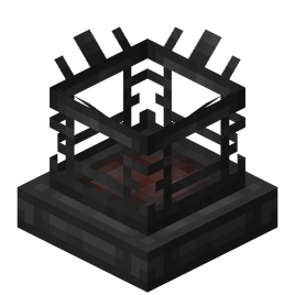 |
| Here’s what an empty blaze burner looks like |
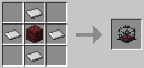 |
| And this is the recipe |
To place the blaze inside the empty “cage,” you need to right-click
either on a blaze or on a blaze spawner, so it can also be done in
Peaceful mode.
Blaze Burners have 3 stages:
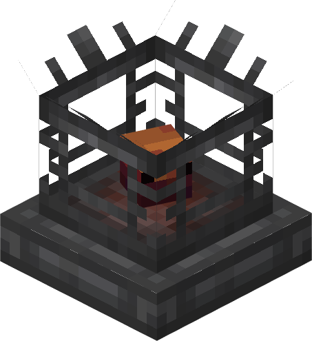 |
| This is the smouldering stage |
 |
| This is the heated stage |
 |
| This is the superheated stage |
SMOULDERING
“Smouldering” means when the Blaze Burner is passive, so when it hasn’t
been given any fuel to consume. Even so, it can still provide a very
small amount of heat to boilers.
This stage provides a passive heat level (similar to a campfire).
HEATED
“Heated” is when the Blaze Burner has been fueled with a flammable
material (e.g. coal, wood, lava, etc.). For this stage, the best
material to use is lava because it lasts a long time and is very simple
to automate with Create.
This stage provides one heat level for the Blaze Burner.
SUPERHEATED
This is the most powerful stage of all.
To reach this level, a special item is required: the Blaze Cake.
 |
| Here’s what a blaze cake base looks like |
 |
| And this is the recipe |
 |
| This is the blaze cake |
 |
| And this is the recipe |
With this stage, all Mixer recipes are unlocked — in particular, it
enables the ability to craft Brass.
This stage provides 2 heat levels per Blaze Burner.
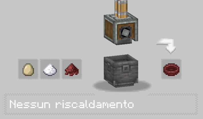
OTHER USES
Blaze Burners are not only used as a heat source for boilers, but also
for Bulk Smoking and Bulk Haunting. To use them in these cases, you need
to light the empty cage with Flint and Steel so that a Campfire flame
appears.
For Bulk Haunting, you need to feed it either Soul Sand or Soul Soil, which
will create a blue Campfire flame inside the cage.
3. WATER INPUT
 |
| This is what it looks like |
This part is the final one — but not the least important — it’s where the
water is inserted.
However, this design is not very efficient and doesn’t perform its function
very well, so we decided to analyze another design instead, which is more efficient
and properly does what it’s supposed to do.
 |
| This is what it looks like |
The difference between the first and the second design is only one — but a
very important one: the “buffer” fills up. It may seem like a small
detail, but it’s actually super useful because this design truly does what
it’s meant to do: serve as a backup.
It’s made up of several blocks, each one crucial:
- 18 water tanks
- 1 steam engine
- 3 shafts
- 2 rotation speed controllers
- 2 large cogs
- 6 cogs
- 4 mechanical pumps
- 4 copper pipes
WATER TANKS
In this case, the tanks serve as a buffer.
This part is extremely important because if, for any reason, the infinite water
sources disappear, there will still be a bit of water that keeps the boiler
running longer. In combination with the rear engine, this allows the boiler
to never shut off—except when, for any reason, there are no more infinite water
sources, in which case the operation will only be temporary.
STEAM ENGINE
This is the most important engine you can put in a boiler.
As mentioned before, each engine is individual, so even if the output system
goes into overstress, the engine behind still provides power to the pumps,
keeping the boiler running and thus avoiding waste of combustible materials
for the blaze burners.
SHAFT
In this case, the shafts are used to connect the steam engine to the two rotation speed controllers, and to connect the two large gears to the smaller gears.
ROTATION SPEED CONTROLLER
These blocks are used, as the name suggests, to regulate the RPM, meaning they can both decrease and increase it.
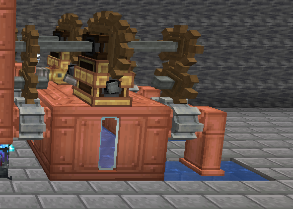
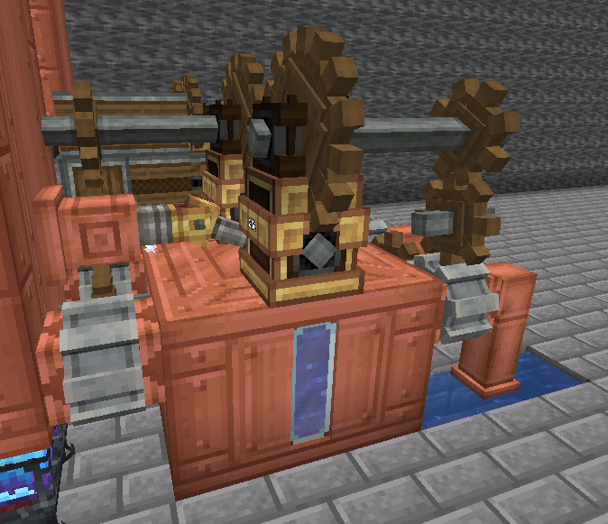
 |
| Here’s what a rotation speed controller looks like |
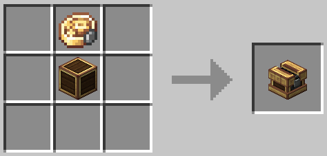 |
| They are crafted using a brass casing and a precision mechanism |
 |
| Here’s what a precision mechanism looks like |
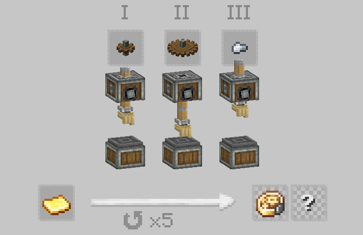 |
| They are crafted using a gold sheet, 5 cogwheels, 5 big cogwheels and 5 iron nuggets |
These blocks are used to regulate not only the rotation speed (from 1 RPM
up to 256 RPM) but also the direction (clockwise and counterclockwise).
However, there is a cost: the inputs and outputs (since there’s more than
one) are in separate blocks. For example, the output (the large gear) in
this case is located in the block above.
Rotation speed controllers are placed next to the shafts, and since they also
function as shafts, they can replace one.
 |
| As in this case |
Using two rotation speed controllers is crucial because it allows the pump
pairs to run at two different speeds.
In fact, the input pair of the buffer runs at 256 RPM, while the input pair
of the boiler runs at 180 RPM (the minimum required for a level 18 boiler),
allowing the buffers to fill up.
LARGE GEARS
The large gears are used to operate the rotation speed controllers,
providing either an input or an output—in this case, an output.
It has 2 recipes
 |
| Here’s what a large cog looks like |
 |
| This is the first one, it uses one shaft and 2 wooden planks |
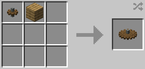 |
| This is the first one, it uses 1 cogwheel and 1 wooden plank |
COGWHEELS
Cogwheels are mainly used, as in this case, to transfer kinetic energy to the pumps.
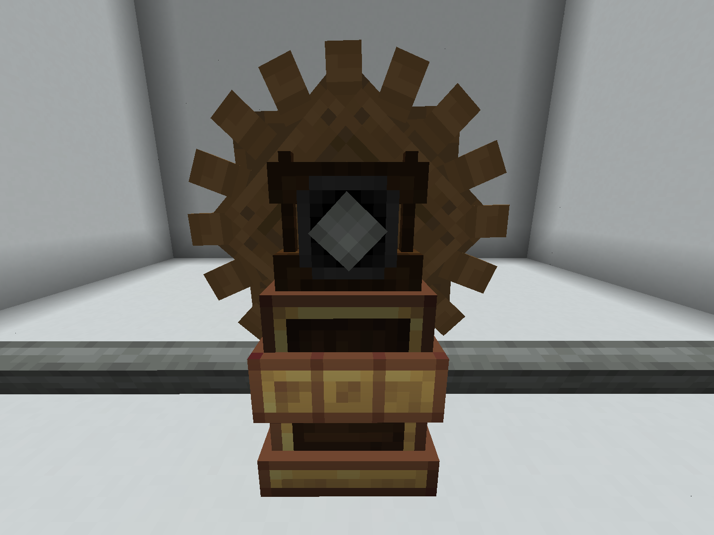
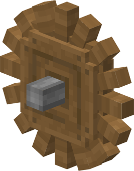
 |
| Here's what a cogwheel looks like |
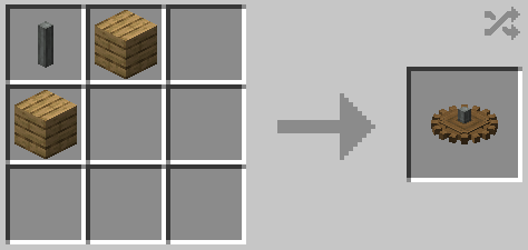
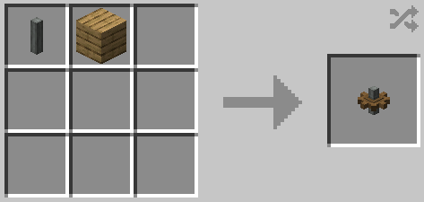 |
| They are crafted using 1 shaft and 1 wooden plank |
Cogwheels, like the encased chain drives, can also transfer kinetic energy vertically, but every time a new gear is placed, the rotation direction changes.
MECHANICAL PUMPS
Mechanical pumps are used to transport liquids through pipes that then end
up in tanks.
To work properly, and to draw water, they need an infinite source.
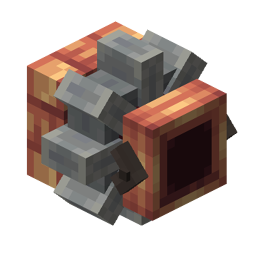 |
| Here’s what a mechanical pump looks like |
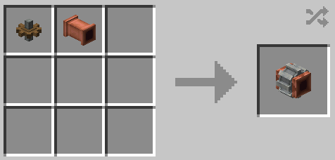 |
| They are crafted using 1 cogwheel and 1 copper pipe |
The rotation direction does not affect the flow direction, but it can be
changed with a wrench.
It can transport fluids up to 16 blocks away (configurable in the Create settings).
Here we introduce a new feature: the impact on stress.
Basically, it’s how many SU it consumes. The impact per pump is: RPM × 4.
So:
- For those running at 256 RPM: 256 × 4 = 1,024 SU
- For those running at 180 RPM: 180 × 4 = 720 SU
Thus, the buffer’s input pair has an impact of: 1,024 × 2 = 2,048 SU
While the boiler’s input pair will have: 720 × 2 = 1,440 SU
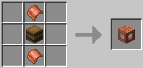
COPPER PIPES
The name is fairly self-explanatory, so it doesn’t need an introduction.
 |
| Here’s what a copper pipe looks like |
 |
| They are crafted using 2 copper sheet and 1 copper ingot |
They can also be crafted by placing copper plates vertically instead of
horizontally.
In this case, their use is to connect infinite water sources to the pumps.
CONCLUSIONS
With this, you know the components of a boiler and how they work. Try different layouts, play with rotation speeds and gear setups, and see how far you can push your system efficiently!